Hard Drive Clock
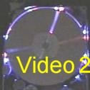
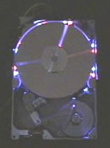 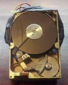 The left image is the clock running in the dark, the one on the right is the clock at rest. There are more pictures and videos below. The left image is the clock running in the dark, the one on the right is the clock at rest. There are more pictures and videos below. |
Have an old hard drive that no longer works? As long as it still spins up chances are you could build a clock out of your old hard drive!
You will need some electronic knowledge, some common electronic components and a bit of
patience. The clock that is produced isn’t exactly practical since most hard drives (especially older ones) are too loud for a clock that is to operate 24 hours a day.
VIDEOS
 Watch a video (1.5MB) of the clock in operation!It takes the clock a sew seconds for the speed to stabilize, during this time there is a random pattern of lights that is displayed. After this the clock starts up. It is shown starting at 2:40:00. Watch a video (1.5MB) of the clock in operation!It takes the clock a sew seconds for the speed to stabilize, during this time there is a random pattern of lights that is displayed. After this the clock starts up. It is shown starting at 2:40:00. |
 Another video (4.7MB) this one shows the clock time being set.Three buttons on the back allow clock adjustment. The purple second hand resets to the zero mark when it’s button is pressed. The blue minute hand increments through each minute and the red hour hand increments through each hour. The position of the hour hand is also dependent on the minute hand. For example the time is 2:30 the hour hand will be pointing at the 12 minute mark. Another video (4.7MB) this one shows the clock time being set.Three buttons on the back allow clock adjustment. The purple second hand resets to the zero mark when it’s button is pressed. The blue minute hand increments through each minute and the red hour hand increments through each hour. The position of the hour hand is also dependent on the minute hand. For example the time is 2:30 the hour hand will be pointing at the 12 minute mark. |
OVERVIEW
- Uses 12 high power LEDs for displaying the clock hands, 6 Blue and 6 Red.
- Slot cut into upper drive platter and white tape on center drive platter provides a slot that when illuminated by the LEDs will represent a clock hand.
- Minute hand is represented by blue light, hour hand is represented by red light and the second hand is represented by purple (both blue and red on at the same time).
- Infrared Beam sensor and drilled index hole in lower drive platter.
- Three micro switches to set hours, minutes and seconds.
- Custom programmed PIC16F628 microcontroller to control clock operation.
Be informed when new projects are available or additional project information is posted by signing up to our mailing list.
STEPS TO CONSTRUCT CLOCK
1) Select Drive: Find an old hard drive that can spin up when power is connected, you may have to disconnect the 40 pin data cable to see that it can spin up. The drive must spin counter clockwise.
2) Open Drive: Open the drive and see that there are three platters in the unit. We will need three since the top one will have a slot cut into it, the second one will have a piece of white tape (or some other highly reflective material attached. And the third platter will have an index hole drilled into it, this index hole will be used to determine where the slot is when it is spinning. It could still work using a two platter drive but the top of the infrared beam sensor would be visible when a hand is over it.
3) Cut Slot: Remove the screw in the center of the platters, this should allow the platters to be removed. Cut a slot into the 1st platter, I clamped the platter into a vice protecting the surface with cardboard so it wouldn’t scratch. A grinder was then used to cut the grove. It was very easy to cut since it was made of aluminum. NOTE: The top platter that I ended up using was from a more modern drive. The older drive had platters that were dark brown and not very reflective, the modern drive had platters that had a silver mirror finish.
4) Drill index hole: Drill a ¼ inch hole near the edge of the 3rd platter. The infrared beam sensor will be positioned around this last platter so make sure that the index hole is in a location that will trip the beam. This optical beam sensor (also known as an optical interrupt switch) is made up of two separate electronic units combined in one housing. The sensor is in the shape of a horse shoe, an infrared LED is mounted in one half and a phototransistor is mounted in the other. The LED is always powered and emitting infrared light (invisible to the human eye). There are two distinct states that this type of device can detect. When there is no obstruction to the beam the phototransistor conducts allowing the circuit connected to it to sense that the beam is not broken. When the beam of infrared light is obstructed the phototransistor no longer conducts and the circuit will sense this also. This device works very well for the Hard Drive Clock since an index hole drilled in the lower platter is all that is needed to interface this device to the platter assembly. With this installed the PIC chip can detect the exact location of the rotating platters once per revolution.
5) Install the LEDs: Mark and drill holes in the outer case housing for LEDs, I used 12 in total, 6 blue and 6 red. More will give better hand visibility but 12 seems adequate. Make sure the LEDs are super bright type, standard LEDs will not be bright enough to cast a good beam. Drill all holes half way between platters 1 and 2 (top and center). I installed them using hot glue, the glue takes a while to dry, during the drying time I temporarily power them and aimed them for the most effective angle.
6) MOD the R/W Arm: Decide if you want the read write arm assembly in place. Remove it if not desired or cut the arms off so they don’t interfere with the spinning platter with a slot cut into it.
7) Install Infrared Beam Sensor: To install this I used some hot glue and placed it in the lower right area of the drive. Placement does not matter as long as it can “see†the index hole that was cut into the 3rd platter. If you don’t want to purchase this sensor it can be taken out of a variety of old electronic items such as old FAX machines, floppy drives, VCR’s. Chances you have something lying around that has just what you are looking for. The one I used came out of an old 51/4 inch floppy drive.
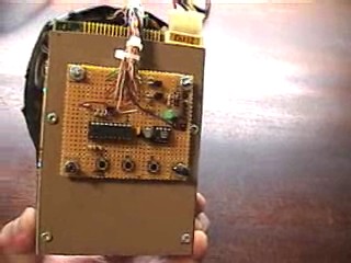
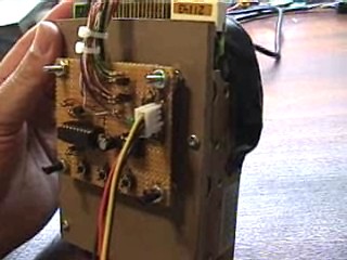
8) Construct and Mount Circuit Board: Use some perf board to create the circuit board, there is a schematic diagram below to show you how to construct it. Find some way to mount the board to the hard drive. I mounted the circuit board to a piece of plastic which was screwed to the back of the hard drive. Connect the wires from the circuit board to the LEDs, infrared beam sensor and the hard drive power input.
9) Program the PIC: Download the PIC microcontroller code and burn it onto the chip using a programmer.
10) Have Fun: Turn it on and set the clock.
POSSIBLE IMPROVEMENTS
- Originally this clock was going to have a real time clock that would keep track of time. It was found that clock accuracy was adequate without this. You will notice that the chip is indeed installed on the board, but it is not currently being used. If it was going to be run for days at a time a RTC would be needed though.
- Smaller LEDs would have been nice, they would eliminate the need for ugly LED cover (black electrical tape). The surface mount ones could probably be mounted onto a strip that is curved and attached to the inside radius of the drive, this would eliminate the need to drill holes in the drive for each LED.
- Make a fancy pattern on the hour… Like a visual cuckoo clock.
SCHEMATIC DIAGRAM
|
Click on the image for a printable size. To get additional information about the PIC 16f628 microcontroller go here. Check out the links for places to buy cheap components! |

DOWNLOAD CODE & BURN METHOD
Here is the HEX file that can be burnt directly to a PIC 16f628 microcontroller. It needs to be burnt to the chip using a programmer. Programmers can be constructed very easily. I initially constructed a no parts programmer to program 16c84 chips but later converted it to program 16f628 chips. There are now much better programmer that can be built or purchased inexpensively. There are some very good free chip burning programs available, Win PIC and FPP are the ones that I use. If you want the source code it is available free of charge from the online store.
CLOCK PICTURES

Front View of Clock


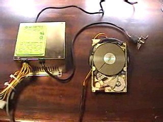
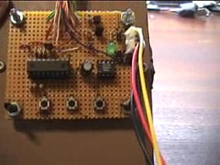
The Power supply that was used is a standard AT type computer power supply.
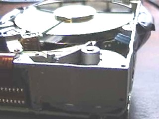
In the upper right area you can see the infrared beam sensor (the one with a 3 conductor ribbon cable coming out of it. You can also see how the read write assembly has had the arms cut off.
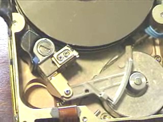
Close up of the infrared beam sensor.
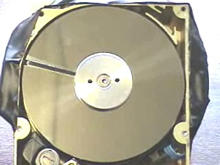
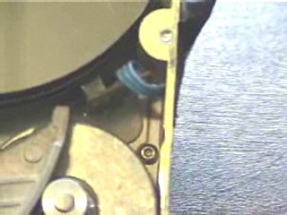
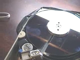
Close up of the 1st drive platter.
Note the white tape (electrical tape) under the slot on the 2nd platter.
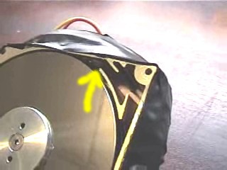
Note the two LEDs that are mounted in the upper right are of the hard drive.

Taken with digital camera, long exposure, lights off.

Taken with a digital camera, normal exposure, lights on.

This diagram shows the various component placements on the clock control board.The real time clock was going to keep track of time however it was found that the PIC could accurately keep track of time over a few hours. That is good enough for right now, the RTC might get connected and programmed in the future.
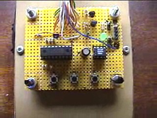
Board close up.
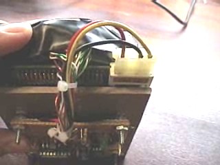
Power harness and LED power bundle, the hard drive power is connected directly to the input power on the control board, as soon as the power supply is turned on the hard drive spins up.
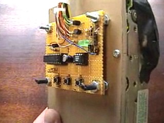
Side view of board.
Note the power cable, typical one that is connected to a floppy drive.
The LED bundle could be much smaller if I had wired it up differently, I electrically wired the LEDs in 2 parallel pairs of 3 series LEDs (each parallel pair has it’s own current limiting resistor). I made all of the connection on the circuit board, with used 24 individual wires (2 per LED. If I did it again I would of wired each series set of 3 LEDs together on the physical clock, this would only need 8 wires from the clock to the circuit board (and only 6 if the first LED cathodes of each color were made common)
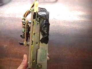
Side view, note the plastic board that was used to mount the clock control board to. Black tape was used to cover the outside of the LEDs.


I left the standoffs a bit long, this meant that the clock could be left on it’s back or angled like a desk clock.